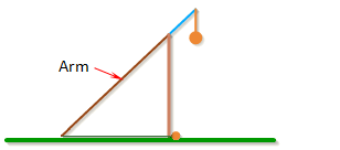
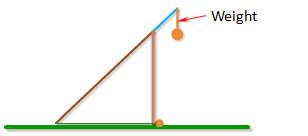
Arm Lengths
The arm of the trebuchet is comprised of two sections: the long component of the arm which is the section that goes from the pivot point to the end where the sling attaches to the arm, and the short component which is the section that goes from the pivot to the end where the weight attaches.
The length of the long component of the arm is called Length of Long Arm.
The length of the short component of the arm is called Length of Short Arm.
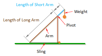
The optimal ratio between the long part of the arm and the short part of the arm will depend mainly on the Mass of Weight. If the weight is very heavy, the long part of the arm can be many times the length of the short part of the arm, which would allow the projectile to attain high velocities.
Height Of Pivot
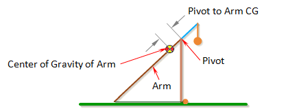
Height of Pivot is the distance from the ground to the pivot.
The pivot is where the arm connects to the frame of the trebuchet, and the point about which the arm rotates.
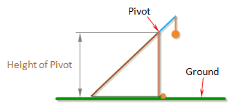
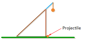
Note: To prevent the weight from hitting the ground, the height of the pivot should be greater than the sum of the Length of Short Arm and the total length of the weight.
Length of Sling
Length of Sling is the length of the sling that connects the projectile to the arm.
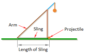
In general, the trebuchet works best if the dimension Length of Sling is just a little less than the dimension Length of Long Arm.
Length of Weight
Length of Weight is the distance from the end of the arm to the
center of gravity of the weight.
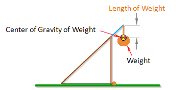
Note: If Length of Weight is set to zero, the simulation uses a different set of equations that assume the weight is rigidly attached to the arm. This is how you simulate a fixed weight trebuchet.
Uniform Arm
When Uniform Arm is selected the program makes the assumption that the arm has a uniform cross-section along its whole length. If the arm has a uniform cross-section then its center of gravity is exactly in the center of the arm and the program can automatically calculate the value for Pivot to Arm CG. The value Inertia of Arm can also be automatically calculated if the arm has a constant cross-sections.
While the Uniform Arm option is convenient, most real trebuchets usually have a tapered arm which tends to have better performance.
Mass of Arm
Mass of Arm is the mass of the entire arm, which includes the parts defined by Length of Short Arm and Length of Long Arm.
For the best performance, the arm should be as light as possible.
Inertia of Arm
Inertia of Arm is the moment of inertia of the entire arm around its center of gravity.
For an arm with a uniform cross-section along its length, the moment of inertia can be approximated by the formula,

where m is the mass of the arm, and L is the total length of the arm (Length of Long Arm + Length of Short Arm).
For a non-uniform arm, the moment of inertia can be found by breaking the arm up into simple shapes, finding the moment of inertia for each one, and then combining them together using the parallel axis theorem. A list of formulas for the moment of inertia of different shapes can be found here. See the Arm Example Calculations.
Alternatly, using a 3D CAD software package is probably the easiest way to find the inertia of a non-uniform arm.
For best performance, the moment of inertia of the arm should be as small as possible. This is why the arm is tapered on many trebuchets.
Note: When Auto Calculate is checked, the arm is assumed to have a uniform cross-section and the Inertia of Arm will be calculated automatically.
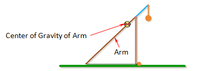
Pivot to Arm CG
Pivot to Arm CG is the distance between the pivot point and the center of gravity of the arm.
The center of gravity of the arm is the average location of the gravitational force acting on the arm. If the arm has a uniform cross-section along its length, then its center of gravity will be located exactly at the center the arm.
For a non-uniform arm, the center of gravity can be found by breaking the arm up into simple shapes, finding the center of mass of each one, and taking the mass-weighted average of the different parts. See the Arm Example Calculations.
Alternately, the center of gravity can be found by hanging the arm horizontally from a string, and moving the string along the arm until it balances. It will balance when the string is at the center of gravity.
For the best performance, the center of gravity of the arm should be as close to the end of the arm that the weight is attached to as possible.
Note: When Auto Calculate is checked, the arm is assumed to have a uniform cross-section and the Pivot to Arm CG will be calculated automatically.
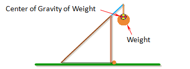
Inertia of Weight
Inertia of Weight is the moment of inertia of the counterweight around its center of gravity.
The moment of inertia can be found by breaking the weight up into simple shapes, finding the moment of inertia for each one, and then combining them together using the parallel axis theorem. A list of formulas for the moment of inertia of different shapes can be found here. The Arm Example Calculations show how to do this for the arm. A similar procedure can be used for the weight.
Alternatly, using a 3D CAD software package is probably the easiest way to find the inertia of the weight.
In general, it is better to have a weight with a small inertia. However a larger inertia comes with a heavier weight. The easiest way to get around this is by having a weight that is able to pivot. If you do this you can set the inertia of the weight to a small number.
Mass of Weight
Mass of Weight is the mass of the counterweight.
In general, the projectile will go farther with a heavier counterweight.
Projectile Type
Selecting a Projectile from the drop down list of projectiles will automatically fill out the Mass of Projectile and Projectile Diameter inputs. If the projectile you are using is not on the list, choose the custom option.
The baseball and golf ball options are special cases. They each have their own curve for calculating the drag coefficient. For all the other options, the simulation uses the smooth sphere curve for calculating the drag coefficient. For more information about calculating the drag coefficient see the Projectile Drag section.
Mass Projectile
Mass of Projectile is the mass of the projectile.
Projectile Diameter
Projectile Diameter is the diameter of the projectile.
Projectile Diameter is used to calculate the drag of the projectile.
If you want to simulate your trebuchet without air resistance, use 0.0 for the Projectile Diameter.
Wind Speed
Wind Speed is the wind speed in the direction the trebuchet is shooting, so if the trebuchet is shooting with the wind, the Wind Speed will be a positive number, and if the trebuchet is shooting into the wind, Wind Speed will be a negative number.
Release Angle
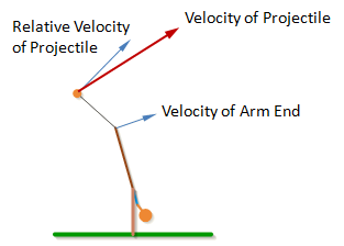
The Release Angle is the angle that the velocity vector of the projectile reaches before the projectile is released.
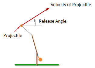
Note: The angle of the velocity of the projectile is not quite the same as the angle of a vector perpendicular to the sling. The angle perpendicular to the sling is the velocity of the projectile relative to the end of the arm, but the end of the arm is also moving, so the velocity of the projectile will be the vector sum of the velocity at the end of the arm and the relative velocity of the projectile.
The projectile typically goes the farthest if the release angle is between 35deg and 40deg.